Surface Blasters Guide
"What every miner should know about Surface Blasting"
TABLE OF CONTENT
- Preface
- Glossary
- Geometric Formulas
- Conversion Table
- Area of rock (m2) per metre blast hole
- Linear charge mass for bulk explosives
- Average weight of various materials blasted
- Typical cup densities to achieve hole density of bulk explosive at given hole depth
- Recommended booster sizes
- Wet vs. dry holes and bottom pumping vs. top hole auger/pump
- Surface blast design
- Blasting geometry
- Timing examples
- Secondary breaking
- Priming / decking
- Airblast and ground (blasting) vibration
- Mitigating flyrock risk - field guide
TABLE OF EQUATIONS
- Mass of rock (t)
- Relative Effective Energy (REE)
- Relative Bulk Strength (RBS)
- Fragmentation (Kuz-Ram)
- Technical Powder Factor (Kt)
- Spacing to burden ratio (a)
- Spacing (S)
- Burden (B)
- Charge Length (L)
- Stemming (T)
- Mass of explosives in 8 charge diameters (W)
- Linear charge density (Mc)
- Coupling
- Angled Blast holes
- Burden (B) Angled holes
- Actual Powder Factor (Ka)
- Scaled Distance
- Peak Particle Velocity (Vibration)
- Airblast (reference pressure)
- Airblast (mass of explosives)
PREFACE
The Surface Blasters Guide has been used with great enthusiasm as a reference in mine blasting training syllabi since it was first published. This new edition has been revised to provide greater emphasis on the answers to critical questions that the Blaster encounters both during his day to day blasting activities and during unusual situations. This is a practical reference guide for blasting on surface mining operations.
This booklet, compiled by AECI's Blast Consult, is the first in our new series of “What every Miner should know”. Based on practical experience, this booklet answers most of the questions a miner might ask on the use and application of AECI Mining Explosives range of explosives and initiating systems for Civil, Quarrying and Surface Mining blasting operations.
Advice on the most appropriate explosive and initiating products and its application in the specific mining area should be obtained from the AECI Offices, sales support and technical teams and/or the website.
DISCLAIMER AND INDEMNITY: Any recommendations given by AECI or any subsidaries, in respect of this document are given in good faith based on information provided. AECI does not, however, warrant that particular results or effects will be achieved if the recommendations are implemented, due to potentially unknown aspects and/or conditions. AECI further does not accept liability for any losses or damages that may be suffered, as a result of the customer acting, or failing to act, on the recommendations given.
GLOSSARY
| TERM | DESCRIPTION |
| Airblast | Shock wave travelling through the air resulting from the detonation of explosives or face/bench movement |
| Back break | Rock broken beyond the limits of the last row and design |
| Borehole pressure | The pressure which the gases of detonation exert on the borehole wall |
| Booster | Also known as Pentolite Primer once a detonator is inserted. Explosive unit, link between the small low energy detonator and the massive but relatively insensitive explosive charge. Core purpose of the primer is to deliver a sufficiently energetic impulse to launch full detonation velocity |
| Burden | Distance between two adjacent rows of drill holes where a free face is available and being used for the blast design, the distance between the toe position of the first or front line of drill holes and the free face |
| Charge mass | The amount of explosive charge in kilograms |
| Clean crushed stone | Crushed stone supplied that is free of fine material and of a known mean size and size distribution |
| Column charge | Length of an explosive charge including any portion of the hole drilled below the design grade |
| Critical diameter | The minimum diameter at which the explosives will reliably initiate or a full column detonation |
| Cut-offs | A portion of an explosive column that has failed to detonate due to rock or ground movement (geological displacement). The initiation system has failed to propagate the whole blast due to a cut-off in the system as a result of flyrock, ground movement, or system failure |
| Decoupling | The use of explosive products having smaller volume than the volume of the blast hole it occupies |
| Delay blasting | The use of delay detonators or connectors to separate charges by a defined |
| Density | Mass per unit volume |
| Detonation pressure | The pressure created in the reaction zone of a detonating explosive |
| Drill cuttings | Material found on bench surface which usually results from the drilling |
| Explosive | Commercial explosives are chemicals and chemical mixtures which, when properly initiated, are rapidly converted into gases at high temperature and pressure. Unconfined, a litre of explosive will expand to around 1000 litres in milliseconds. Together with the shock wave of detonation, this results in extremely high breaking stresses in rock. |
| Free face | An unconfined opening located at an optimum distance from the blasthole, enabling the explosive energy to perform the greatest amount of work on the rock mass. A blast will be more efficient if it has two free faces rather than one |
| Flyrock | Rock that is propelled through air from a blast |
| Fragmentation | Measure to describe the size of distribution of broken rock after blasting |
| Ground vibration | Ground movement caused by the stress waves emanating from a blast |
| Initiation | The act of detonating explosives by appropriate means |
| Line drilling | A method of overbreak control which uses a series of closely spaced holes that are not charged |
| Loading density | The mass of explosives per metre of borehole |
| Maximum Instantaneous Charge or Mass per delay | Mass of explosive detonating in some defined time period, usually 8 milliseconds for pyrotechnics, less for electronics |
| Overbreak | Excessive breakage of rock beyond the desired excavation limit |
| Peak Particle Velocity (PPV) | Ground vibration is measured in terms of Peak Particle Velocity (PPV) with units in mm/s or mm/s-1. It should be noted that the PPV refers to the movement within the ground of molecular particles and not surface movement. The displacement value in mm refers to the movement of particles at the surface (surface movement) |
| Pre-split | A controlled blast in which decoupled charges are fired in holes on the perimeter of the excavation prior to the main firing |
| Primer | A booster or cartridge explosives used to initiate other explosives or blasting agents which includes a detonator or detonating cord |
| Relative Bulk Strength (RBS) | The energy yield per unit volume of an explosive compared to ANFO |
| Relative Weight Strength | The energy yield per unit mass of an explosive compared to ANFO |
| Spacing | The distance between adjacent drill holes in the same row |
| Stemming | Inert material used to confine the gases generated during detonation |
| Swell factor | The ratio of the volume of broken rock to the volume of in-situ rock |
| Velocity of detonation | The velocity at which a detonation progresses through an explosive |
GEOMETRIC FORMULAS
There are many geometric formulas and they relate height, width, length, or radius, etc. to perimeter area, surface area, or volume, etc. There are some basic formulas that you will need to use:
| DESCRIPTION | SYMBOL |
| Diameter | |
| Radius | |
| Length | |
| Height | |
| Pi (Mathematical constant ≈ 3.1416) | |
| Circumference of circle: | |
| Area of circle: | |
| Area of rectangle: | |
| Area of triangle: | |
| Volume of wedge: | |
| Volume of cylinder: | |
| Volume of cone: |
CONVERSION TABLE
| THIS UNIT | MULTIPLIED BY FACTOR | CONVERTS TO | ||
| LENGTH | ||||
| metres | m | 3.28 | feet | ft |
| metres | m | 39.370 | inches | in |
| millimetres | mm | 0.0397 | inches | in |
| kilometres | km | 0.621 | miles | mi |
| MASS | ||||
| kilogram | kg | 2.20 | pound | lb |
| metric tonne | t | 1.1 | short ton | tn |
| gram | g | 0.035 | avoirdupois | av |
| gram | g | 0.032 | Troy ounce | oz |
| gram | g | 16.67 | grain | gr |
| ENERGY | ||||
| Joule | J | 0.24 | calorie | cal |
| Joule | J | 0.74 | foot-pound | ft-lb |
| calorie | cal | 3.09 | foot-pound | ft-lb |
| kilowatt | kW | 1.341 | horse power | hp |
| VOLUME | ||||
| cubic centimetre | cm3 or cc | 0.06 | inch | in3 |
| cubic metre | m3 | 1.31 | yard3 or cubic yard | yd3 |
| cubic metre | m3 | 33.33 | cubic feet | ft3 |
| litre | l | 0.264 | US gallon | gal |
| cubic centimetre | cm3 or cc | 0.034 | fluid-ounce | fl oz |
| DENSITY | ||||
| Kilogram per cubic metre | kg/m3 | 0.062 | Pound per cubic foot | lbs/ft3 |
| Gram per cubic centimetre | g/cm3 | 62.43 | Pound per cubic foot | lbs/ft3 |
| POWDER FACTOR | ||||
| Kilogram per cubic metre | kg/m3 | 0.752 | Pound per cubic yard | lbs/yd3 |
| SPEED | ||||
| Metre per second | m/s | 3.28 | foot per second | ft/s or fps |
| Millimetre per second | mm/s | 0.039 | Inch per second | in/s |
| Kilometre per Hour | km/H | 0.6 | Miles per Hour | mi/H or mph |
| PRESSURE | ||||
| Kilopascal | kPa | 0.145 | Pound per Square Inch | psi |
| Atmosphere | atm | 14.7 | Pound per Square Inch | psi |
| bar | 14.5 | Pound per Square Inch | psi | |
| Kilopascal | kPa | 0.01 | bar | |
| TEMPERATURE | ||||
| Fahrenheit (f) | F | (f-32)x5/9 | Centigrade | oC |
| Centigrade (c) | oC | (c+32)x9/5 | Fahrenheit | F |
| AREA | ||||
| Square centimetre | cm2 | 0.16 | Square inch | in2 |
| Square metre | m2 | 1550 | Square inch | in2 |
| Square metre | m2 | 11.11 | Square foot | ft2 |
AREA OF ROCK (m2) PER METRE BLAST HOLE
| BURDEN (m) | ||||||||||||||||
| 1 | 2 | 3 | 4 | 5 | 6 | 7 | 8 | 9 | 10 | 11 | 12 | 13 | 14 | 15 | SPACING (m) | |
| 1 | - | - | - | - | - | - | - | - | - | - | - | - | - | - | 1 | |
| - | 4 | - | - | - | - | - | - | - | - | - | - | - | - | - | 2 | |
| - | 6 | 9 | - | - | - | - | - | - | - | - | - | - | - | - | 3 | |
| - | - | 12 | 16 | - | - | - | - | - | - | - | - | - | - | - | 4 | |
| - | - | - | 20 | 25 | - | - | - | - | - | - | - | - | - | - | 5 | |
| - | - | - | 24 | 30 | 36 | - | - | - | - | - | - | - | - | - | 6 | |
| - | - | - | - | 35 | 42 | 49 | - | - | - | - | - | - | - | - | 7 | |
| - | - | - | - | - | 48 | 56 | 64 | - | - | - | - | - | - | - | 8 | |
| - | - | - | - | - | 54 | 63 | 72 | 81 | - | - | - | - | - | - | 9 | |
| - | - | - | - | - | - | 70 | 80 | 90 | 100 | - | - | - | - | - | 10 | |
| - | - | - | - | - | - | - | 88 | 99 | 110 | 121 | - | - | - | - | 11 | |
| - | - | - | - | - | - | - | 96 | 108 | 120 | 132 | 144 | - | - | - | 12 | |
| - | - | - | - | - | - | - | - | 117 | 130 | 143 | 156 | 169 | - | - | 13 | |
| - | - | - | - | - | - | - | - | - | 140 | 154 | 168 | 182 | 196 | - | 14 | |
| - | - | - | - | - | - | - | - | - | 150 | 165 | 180 | 195 | 210 | 225 | 15 | |
Note: Table based on a spacing = a x burden using a value of a = 1.0 to 1.5. Where “-”, this could be considered an unusual geometry or combination requiring the Blaster to review the pattern.
Volume of rock blasted (m3)
| Per metre of hole | |
| Per hole |
LINEAR CHARGE MASS FOR BULK EXPLOSIVES (kg/m)
| HOLE DIAMETER | DENSITY OF EXPLOSIVES (g/cc) | ||||||||||||
| Inch | mm | 0.75 | 0.80 | 0.85 | 0.90 | 0.95 | 1.00 | 1.05 | 1.10 | 1.15 | 1.20 | 1.25 | 1.30 |
| 3 | 76 | 3.40 | 3.63 | 3.86 | 4.08 | 4.31 | 4.54 | 4.76 | 4.99 | 5.22 | 5.44 | 5.67 | 5.9 |
| 3 1⁄2 | 89 | 4.67 | 4.98 | 5.29 | 5.60 | 5.91 | 6.22 | 6.53 | 6.84 | 7.15 | 7.47 | 7.78 | 8.09 |
| 4 | 102 | 6.13 | 6.54 | 6.95 | 7.35 | 7.76 | 8.17 | 8.58 | 8.99 | 9.40 | 9.81 | 10.21 | 10.62 |
| 4 1⁄4 | 108 | 6.87 | 7.33 | 7.79 | 8.24 | 8.70 | 9.16 | 9.62 | 10.08 | 10.54 | 10.99 | 11.45 | 11.91 |
| 4 1⁄2 | 114 | 7.66 | 8.17 | 8.68 | 9.19 | 9.70 | 10.21 | 10.72 | 11.23 | 11.74 | 12.25 | 12.76 | 13.27 |
| 4 7⁄8 | 124 | 9.06 | 9.66 | 10.26 | 10.87 | 11.47 | 12.08 | 12.68 | 13.28 | 13.89 | 14.49 | 15.10 | 15.70 |
| 5 | 127 | 9.50 | 10.13 | 10.77 | 11.40 | 12.03 | 12.67 | 13.30 | 13.93 | 14.57 | 15.20 | 15.83 | 16.47 |
| 5 1⁄8 | 130 | 9.97 | 10.63 | 11.30 | 11.96 | 12.63 | 13.29 | 13.96 | 14.62 | 15.29 | 15.95 | 16.62 | 17.28 |
| 5 1⁄4 | 133 | 10.47 | 11.16 | 11.86 | 12.56 | 13.26 | 13.96 | 14.65 | 15.35 | 16.05 | 16.75 | 17.44 | 18.14 |
| 5 1⁄2 | 140 | 11.55 | 12.32 | 13.08 | 13.85 | 14.62 | 15.39 | 16.16 | 16.93 | 17.70 | 18.47 | 19.24 | 20.01 |
| 5 5⁄8 | 143 | 12.05 | 12.85 | 13.65 | 14.45 | 15.26 | 16.06 | 16.86 | 17.67 | 18.47 | 19.27 | 20.08 | 20.88 |
| 5 7⁄8 | 149 | 13.08 | 13.95 | 14.82 | 15.69 | 16.56 | 17.44 | 18.31 | 19.18 | 20.05 | 20.92 | 21.80 | 22.67 |
| 6 | 152 | 13.61 | 14.52 | 15.42 | 16.33 | 17.24 | 18.15 | 19.05 | 19.96 | 20.87 | 21.78 | 22.68 | 23.59 |
| 6 1⁄4 | 159 | 14.89 | 15.88 | 16.88 | 17.87 | 18.86 | 19.86 | 20.85 | 21.84 | 22.83 | 23.83 | 24.82 | 25.81 |
| 6 1⁄2 | 165 | 16.04 | 17.11 | 18.18 | 19.24 | 20.31 | 21.38 | 22.45 | 23.52 | 24.59 | 25.66 | 26.73 | 27.80 |
| 6 3⁄4 | 171 | 17.22 | 18.37 | 19.52 | 20.67 | 21.82 | 22.97 | 24.11 | 25.26 | 26.41 | 27.56 | 28.71 | 29.86 |
| 7 3⁄8 | 187 | 17.22 | 18.37 | 19.52 | 20.67 | 21.82 | 22.97 | 24.11 | 25.26 | 26.41 | 27.56 | 28.71 | 29.86 |
| 7 5⁄8 | 194 | 22.17 | 23.65 | 25.13 | 26.60 | 28.08 | 29.56 | 31.04 | 32.52 | 33.99 | 35.47 | 36.95 | 38.43 |
| 7 7⁄8 | 200 | 23.56 | 25.13 | 26.70 | 28.27 | 29.85 | 31.42 | 32.99 | 34.56 | 36.13 | 37.70 | 39.27 | 40.84 |
| 8 1⁄2 | 216 | 27.48 | 29.31 | 31.15 | 32.98 | 34.81 | 36.64 | 38.48 | 40.31 | 42.14 | 43.97 | 45.80 | 47.64 |
| 9 | 229 | 30.89 | 32.95 | 35.01 | 37.07 | 39.13 | 41.19 | 43.25 | 45.31 | 47.37 | 49.42 | 51.48 | 53.54 |
| 9 7⁄8 | 251 | 37.11 | 39.58 | 42.06 | 44.53 | 47.01 | 49.48 | 51.95 | 54.43 | 56.90 | 59.38 | 61.85 | 64.33 |
| 10 | 254 | 38.00 | 40.54 | 43.07 | 45.60 | 48.14 | 50.67 | 53.20 | 55.74 | 58.27 | 60.80 | 63.34 | 65.87 |
| 10 5⁄8 | 270 | 42.94 | 45.80 | 48.67 | 51.53 | 54.39 | 57.26 | 60.12 | 62.98 | 65.84 | 68.71 | 71.57 | 74.43 |
| 11 | 279 | 45.85 | 48.91 | 51.97 | 55.02 | 58.08 | 61.14 | 64.19 | 67.25 | 70.31 | 73.36 | 76.42 | 79.48 |
| 12 1⁄2 | 311 | 56.97 | 60.77 | 64.57 | 68.37 | 72.17 | 75.96 | 79.76 | 83.56 | 87.36 | 91.16 | 94.96 | 98.75 |
| 13 | 330 | 64.15 | 68.42 | 72.70 | 76.98 | 81.25 | 85.53 | 89.81 | 94.08 | 98.36 | 102.64 | 106.91 | 111.19 |
| 13 3⁄4 | 349 | 71.75 | 76.53 | 81.31 | 86.10 | 90.88 | 95.66 | 100.45 | 105.23 | 110.01 | 114.79 | 119.58 | 124.36 |
| 15 | 381 | 85.51 | 91.21 | 96.91 | 102.61 | 108.31 | 114.01 | 119.71 | 125.41 | 131.11 | 136.81 | 142.51 | 148.21 |
| 16 | 406 | 97.10 | 103.57 | 110.04 | 116.52 | 122.99 | 129.46 | 135.93 | 142.41 | 148.88 | 155.35 | 161.83 | 168.30 |
| 16 1⁄2 | 419 | 103.41 | 110.31 | 117.20 | 124.10 | 130.99 | 137.89 | 144.78 | 151.67 | 158.57 | 165.46 | 172.36 | 179.25 |
| 17 1⁄2 | 445 | 116.65 | 124.42 | 132.20 | 139.98 | 147.75 | 155.53 | 163.30 | 171.08 | 178.86 | 186.63 | 194.41 | 202.19 |
Note: All calculations are based on the metric drill bit sizes. The linear charge density of Bulk Explosives is determined by the final hole diameter which is affected by the wear of the drill bit and the softness of the rock formation. *Red zone - please consult your AECI office for advice on the appropriate product.
AVERAGE WEIGHT OF VARIOUS MATERIALS BLASTED (DENSITY OF ROCK TYPE)
| Material | Relative Density | Weight (solid) | Weight (broken) | ||
| t/m3 | m3/t | t/m3 | m3/t | ||
| Anthracite (Coal) | 1.3 - 1.8 | 1.60 | 0.63 | 1.04 | 0.96 |
| Basalt | 2.8 - 3.0 | 3.04 | 0.33 | 2.00 | 0.5 |
| Bituminous Coal | 1.2 - 1.5 | 1.36 | 0.74 | 0.88 | 1.1 |
| Diabase | 2.6 - 3.0 | 2.80 | 0.36 | 1.84 | 0.54 |
| Diorite | 2.8 - 3.0 | 2.96 | 0.34 | 1.92 | 0.52 |
| Dolomite | 2.8 - 2.9 | 2.88 | 0.35 | 1.84 | 0.54 |
| Gneiss | 2.6 - 2.9 | 2.88 | 0.35 | 1.84 | 0.54 |
| Granite | 2.6 - 2.9 | 2.72 | 0.37 | 1.76 | 0.57 |
| Gypsum | 2.3 - 3.3 | 2.88 | 0.35 | 1.84 | 0.54 |
| Hematite (Iron Ore) | 4.5 - 5.3 | 4.88 | 0.20 | 3.20 | 0.31 |
| Limestone | 2.4 - 2.9 | 2.64 | 0.38 | 1.68 | 0.60 |
| Limonite (Iron Ore) | 3.6 - 4.0 | 3.76 | 0.27 | 2.48 | 0.40 |
| Magnesite | 3.0 - 3.2 | 3.2 | 0.31 | 2.00 | 0.50 |
| Magnetite (Iron Ore) | 4.9 - 5.2 | 5.04 | 0.20 | 3.28 | 0.30 |
| Marble | 2.1 - 2.9 | 2.48 | 0.40 | 1.60 | 0.63 |
| Mica-Schist | 2.5 - 2.9 | 2.72 | 0.37 | 1.76 | 0.57 |
| Porphyry | 2.6 - 2.6 | 2.56 | 0.39 | 1.68 | 0.60 |
| Quartzite | 2.0 - 2.8 | 2.56 | 0.39 | 1.68 | 0.60 |
| Rock Salt | 2.1 - 2.6 | 2.32 | 0.43 | 1.52 | 0.66 |
| Sandstone | 2.0 - 2.6 | 2.40 | 0.42 | 1.52 | 0.66 |
| Shale | 2.4 - 2.8 | 2.56 | 0.39 | 1.68 | 0.60 |
| Silica Sand | 2.2 - 2.8 | 2.56 | 0.39 | 1.68 | 0.60 |
| Slate | 2.5 - 2.8 | 2.72 | 0.37 | 1.76 | 0.57 |
| Talc | 2.6 - 2.8 | 2.64 | 0.38 | 1.76 | 0.57 |
| Trap Rock | 2.6 - 3.0 | 2.80 | 0.36 | 1.84 | 0.54 |
Note: Based on practical field experience
Mass of Rock (t)
Click for Calculator
TYPICAL CUP DENSITIES TO ACHIEVE AVERAGE IN HOLE DENSITY OF BULK EXPLOSIVE AT A GIVEN HOLE DEPTH
AECI Mining Explosives manufactures a wide range of emulsion based explosives to optimise blasting in soft to hard rock conditions, manage reactive and non-reactive rock types and extreme conditions such as burning coal.
Cup samples are taken at regular intervals during the charging process to enable a visual confirmation that the product is being mixed correctly and, where appropriate, is being gassed to achieve the required average in-hole density for the site specific blast design.
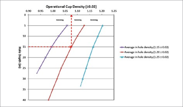
The following graph illustrates that in order to maintain the average in-hole density for the required blast design, the operational cup density ranges are reduced with increasing hole depth. If we are for example charging a 15m hole depth, then we would read horizontally across the graph to where the line intersects the required average in-hole density line, say 1.20 and then vertically up to read the operational cup density of 1.08.
A site specific charging table can then be produced by the AECI operational team. This is based on the chosen explosive being used and the blast design requirements on site to manage the operational cup densities to produce the required average in-hole density.
Note: Not exceeding maximum recommended toe density
Relative Effective Energy (REE) or Relative Weight Strength (RWS)
Effective Energy (EE) is calculated as the total energy released by the explosive gases as they expand and do useful work from the initial detonation pressure down to a cut-off pressure of 20 Mpa, compared to Anfo.
Click for Calculator
Note: Where EE = Effective Energy @ 20MPa (MJ/kg) ANFO – 0.8 g/cc (94.3% AN 5.7% FO), 2.9 MJ/kg
Relative Bulk Strength (RBS)
Click for Calculator
Note: Where ρ = Relative density ANFO – 0.8 g/cc (94.3% AN 5.7% FO), 2.9 MJ/kg
RECOMMENDED BOOSTER SIZES
Boosters have been developed to initiate the range of AECI Mining Explosives bulk explosives. As a result of their high density (approximately 1.65g/cm3) and very high velocity of detonation, VoD, around 7000m/s, these primers, despite its small size, develop extremely high peak pressures during detonation. Boosters are typically cylindrical in shape and will completely enclose all the AECI range of detonators and have been developed for use with detonating cord.
AECI advocates the use of boosters in the surface mining application as both emulsion packaged cartridge explosives (at a starting VoD ~3700m/s and run up to 4500-5000m/s) and watergel packaged cartridges explosives (3500-3700m/s) tend not to have enough kick to get the bulk emulsion reliably started.
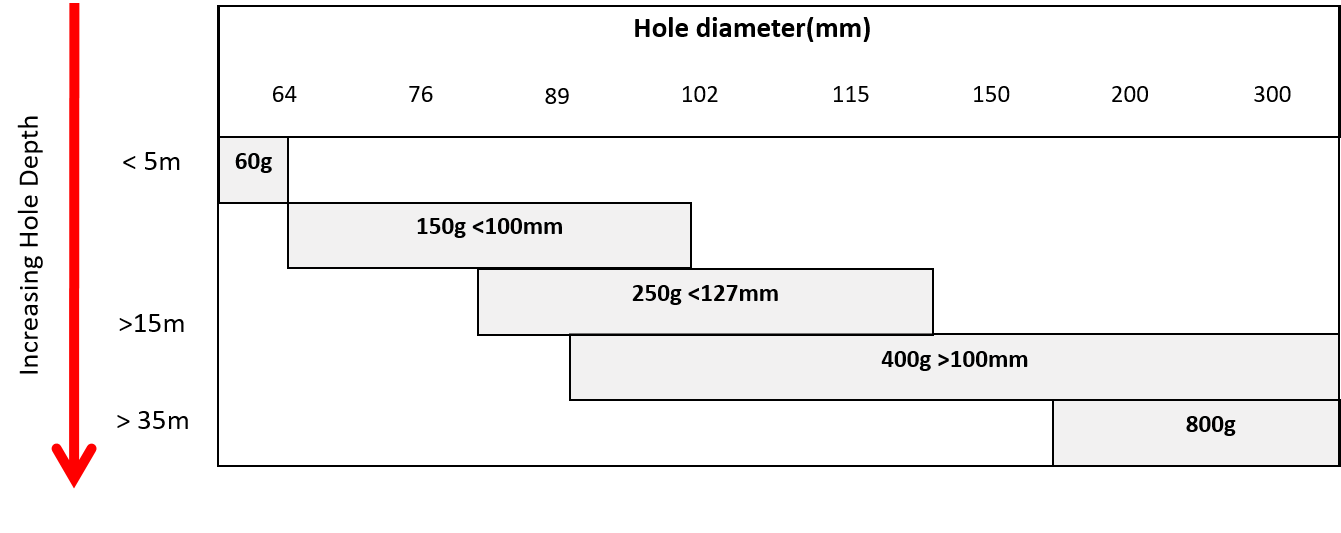
* AECI recommends the use of the largest booster possible. Using a 400g in hole < 100mm, consider fit for explosives, initiating system and water.
WET VS. DRY DRILL HOLES AND BOTTOM PUMPING VS. TOP HOLE AUGER/ PUMP
A wet hole is defined as where the depth of water in the hole exceeds 5% of the hole depth.
Top load emulsions in dry hole > 120mm
Concerns:
- Bridging of produst in hole
- Hole depth < 10m

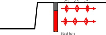
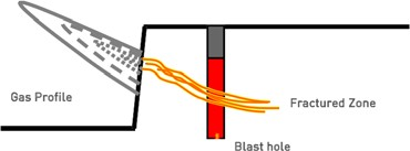
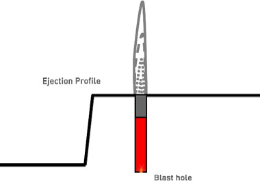
SURFACE BLAST DESIGN
Blast pattern design is primarily governed by the objectives of blasting, which is inevitably to deliver a good broken (fragmented) rock result at acceptable cost. The fixed parameters are usually the rock type, the production rate, the bench height, the drilling and loading equipment and the range of explosives.
The required blast design must accommodate these limitations by specifying the drilling pattern, loading instructions and initiation design. The overriding importance in arriving at these requirements are the combination of hole diameter and blasting powder factor, which not only control the blasting effects, but also determines the overall explosive and drilling efficiency.
There are a variety of approaches in deriving at blasting patterns. Most importantly for all interested parties, however, is the end result of the relationship between the mass of explosives and volume of ground broken for a particular breaking effect.
The following process will enable a blaster to arrive at a robust design to enable the rock to be successfully broken. The design can then be adjusted to align the required fragmentation and/or muckpile movement to control dilution and/or Load and Haul.
The figure below illustrates the various aspects of a blast design and the relevant terminology applied to it.
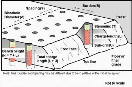
Terminology and Nomenclature
Effective Energy (EE) is calculated as the total energy released by the explosive gases as they expand and do useful work from the initial detonation pressure down to a cut-off pressure of 20 Mpa, compared to Anfo.
| Description | Symbol | Units |
| Rock Factor | A | - |
| Spacing to Burden ratio | a | - |
| Burden | B | m |
| % Coupling | C | - |
| Explosive diameter | d | mm |
| Hole diameter | D | mm |
| Relative Weight Strength | RWS | - |
| Relative Effective Energy | REE | - |
| Bench height | H | m |
| Actual Powder Factor | Ka | kg/m3 |
| Technical Powder Factor | Kt | kg/m3 |
| Explosive column above grade | L | m |
| Linear charge density | Mc | kg/m |
| Relative density of explosive | ρ | - |
| Spacing | S | m |
| Stemming length | T | m |
| Subdrill length | U | m |
| Mass per delay | E | kg/delay |
Management and prediction of fragmentation
The primary purpose of blasting is to fragment rock and there are significant rewards for delivering a fragmentation size range which is not only well suited to the mining system it feeds, but also minimises un-saleable fractions and enhances the value of what can be sold. Fragmentation is controlled by a combination of the following factors:
- Understand the influence of the Rock type, Geology and Rock Properties
- Explosive type
- Control shape of “S” curve
- Explosive Mass/Powder factor
- Control mean size of muckpile
- Stemming
- Hole diameter & Bench heights
- Influence oversize
- Rock Breaking process
- Drilling & Crush zone
- Influence fines
- Electronic Initiation
- Control Uniformity of muckpile, reduces oversize and fines
The fragmentation size can be predicted from the following formula:
Click for Calculator
X = Mean size (cm) - 50% passing
A = Rock factor, varying between 0.8 to 22 depending on hardness and structure –
(See Technical Powder Factor) 8 for soft rocks and 14 for hard rocks
Kt = Technical powder factor (excluding sub-drill) (kg/m3)
Q = Mass of explosive in blast hole (excluding sub-drill) (kg)
RWS = Relative Weight Strength of the explosive (115 being RWS of TNT)
Technical Powder Factor, Kt (kg/m3)
Click for Calculator
| Description | Rock Type | Technical Powder Factor (kg/m3) | Rock Factor | UCS (MPa) |
| Hard | Andesite | 0.70 - 0.90 | 12 - 14 | >250 |
| Dolerite | ||||
| Granite | ||||
| Ironstone | ||||
| Silcrete | ||||
| Medium | Dolomite | 0.40 - 0.50 | 10 - 11 | 100 - 250 |
| Hornfels | ||||
| Quartzite | ||||
| Serpentine* | ||||
| Schist* | ||||
| Soft | Sandstone | 0.25 - 0.35 | 8 - 9 | 50 - 100 |
| Calcrete | ||||
| Limestone | ||||
| Shale | ||||
| VerySoft | Coal | 0.15 - 0.25 | 6 | < 50 |
* These rock types are soft in terms of physical strength but have other characteristics requiring heavier charging than might be expected.
Spacing to Burden ratio, a (No units)
Click for Calculator
| Range | a |
| General | 1.0 - 1.5 |
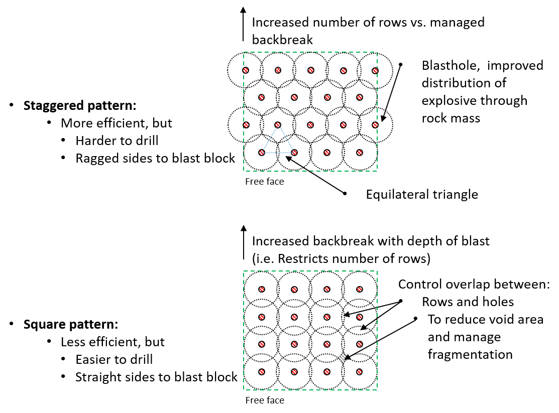
| Square pattern | 1.0 |
| Staggered pattern | 1.15 |
| Armour Stone (Rip-Rap) - Large rocks | 0.7 - 1.0 |
Staggered rows of holes deliver better distribution of the explosive than rows arranged in ranks with a rectangular pattern, as shown in the Figure 2. This means that for the same powder factor the fragmentation will be more uniform for staggered patterns.
A very important consideration in narrow blasts is that a square pattern is efficient for maintaining straight sides, whereas staggered patterns either require extra holes, or leave a zigzag edge.
Square patterns also give more efficient drilling. The drill rig can work back from the free face in a straight line, instead of having to skew between the rows. This is partially overcome by moving the drill rig down rows parallel to the face. A further complication arises when tying in the blast for initiation. With square patterns, it is easier to determine how to tie in the blast, especially when the pattern is close and the ground surface is uneven.
In general, square patterns are desirable for smaller blastholes and in any situation where a tight, straight edge is required for the blast. The larger the block of ground being blasted and the larger the blasthole diameter, the more the benefit of using a staggered pattern.
Comparison of efficiency of drilling patterns
- Forward movement deteriorates towards back
- Fragmentation suffers towards back
- Overbreak gets worst with depth of blast
- Flyrock increases with depth
- Vibrations increase
- Digging gets tighter at back
- Timing concepts remain the same
Spacing, S (m)
Click for Calculator
Burden, B (m)
Click for Calculator
Charge length above grade, L (m)
Click for Calculator
Stemming length, T (m)
Rules of thumb
| Rock type | Normal | Controlled | Stemming |
| Value x hole diameter | |||
| Hard | 20 | 30 | Crushed stone1 |
| Hard | 30 | 40 | Drill cuttings2 |
| Medium (weathered) | 25 | 35 | Crushed stone3 Drill cuttings |
| Soft | 15 | 25 | Drill cuttings4 |
NOTES:
Normal – for general blasting where the risk or impact of an event is low.
Controlled – for sensitive blasting where the risk or impact of an event is high.
1 Clean crushed stone: with a mean size of the stemming material > 1/10th of the hole diameter. e.g. For blast hole diameters in the range 50 to 130 mm, angular crushed rock in the approximate size range of 6 to 13 mm makes a very effective stemming material
2 Drill cuttings: material usually found on bench surface from drilling equipment
3 Crushed stone: tests have shown that it is not as effective as we move from medium to soft rock types, we also experience an increase risk in the potential for flyrock
4 Drill cuttings: Columns shorter than 20D generally cause a higher risk of noise, airblast, flyrock and overbreak
The optimum stemming length depends very largely on rock properties and degree of confinement and can vary from 20 to 60D.
Stemming length is influenced by:
- Rock conditions
- Hole diameter
- Bench height
- Burden
- Explosive strength
- Explosive density
- Charge length
- Flyrock control
- Airblast limitations
Clearly, determination of a safe and efficient design length of stemming requires both good judgement and a period of cautious testing.
Cratering Formulae
The following equation uses the principles of cratering to derive an initial estimate of stemming height rather than using the rules of thumb. As this is not strict cratering, 8 charge diameters are used to derive active charge mass at the top, rather than 6.
Note that if the bench height is less than the indicated stemming length plus 8 diameters, then the hole diameter is excessive for that bench height and an iterative design method is needed.
There is no allowance for rock hardness or burden in the equation since hard rock leaves more gas energy for ejecting stemming, but has generally smaller burdens. This will counter the reduced gas energy but larger burdens of weaker rocks. Local judgement and experiment is key in homing in on the right level of stemming for control of fragmentation and flyrock
Click for Calculator
| Symbol | Description | Unit |
| T | Stemming length | Metre (m) |
| Z | Flyrock factor | Normal blasting = 1.0 Contained blasting = 1.5 |
| W | Mass of explosives in 8 charge diameters, or in column length if this is less | Kilograms (kg) |
| REE | Relative Effective Energy of the explosive | ANFO is taken as 100 |
| D | Hole diameter | mm |
| Note: | Bench height must be more than T + 8 charge diameters | |
Click for Calculator
Linear charge density, Mc (kg/m)
Mass of explosives contained in one meter of charge length
Bulk/Pumpable explosive
Click for Calculator
Soft, Packaged explosive
Need to assess the degree of rupture that occurs when the cartridges are dropped down the hole and whether the hole is wet or dry.
Click for Calculator
Click for Calculator
As a guide, typically a range of 80 to 85% coupling in a dry hole and 65% in a wet hole.
As a starting point, depending on the availability of suitable sized cartridges, the cartridge size would be ¾ of the hole diameter, to prevent damage to the initiating system and to allow the displacement of any water in the blast hole.
Angled Blast holes
If the angle of the blast hole is (measured from the horizontal e.g. vertical hole = 90o)
Then:
Click for Calculator
and
Click for Calculator
Actual Powder factor, Ka (kg/m3 (Vertical holes)
The actual powder factor can be calculated by including the sub-drill in the charge length.
Click for Calculator
Pre-split
-
Spacing = Hole diameter x 12
- Range 10 (Soft) to 15 (Hard)
- Burden = 0.5 x production blast burden (B)
- Uncharged length at top = 10 x D
-
Powder factor = 0.5kg per square metre of face
- Range 0.3 (Soft) to 0.8 (Hard) kg/m2
- Do not stem holes
- Fire all holes on the same delay, or in groups of ≥ 5 holes
- Any water in the blast hole will couple the explosives to the sidewalls of the blasthole and impact on the effectiveness of the result
Blasting Geometry (Rules of Thumb)
Blast designs should always be approached from theoretical principles to ensure sound economic designs, achieve the desired results and to manage critical issues such as airblast, ground vibrations, noise and flyrock.
A rule of thumb is a principle with a broad application that is not intended to be strictly accurate or reliable for every situation. It is, however, easily learned and an easily applied procedure for approximately calculating or recalling some value, or for making some determination on bench.
The following rules of thumb are shared as a quick reference as to whether a practise on bench is sound and will yield the desired results, or as a warning that the robustness of the blast design may need to be further questioned.
| Rules of thumb | ||
| Burden | B | 25 to 35 times the hole diameter |
| Bench height | H |
|
| Spacing | S |
|
| Charge length | L | >20 D |
| Stemming | T | 0.7 to 1.2 times burden |
| Subdrill (if necessary) | U |
|
UK Stiffness Ratio
This ratio gives an indication of blast geometry and the affects of Bench Height/Burden Ratio.
| Stiffness Ratio (H/B) | 1 | 2 | 3 | 4 |
| Fragmentation | Poor | Fair | Good | Excellent |
| Airblast | Severe | Fair | Good | Excellent |
| Flyrock | Severe | Fair | Good | Excellent |
| Ground Vibration | Severe | Fair | Good | Excellent |
| Comments | Severe back break and toe problems. DO NOT BLAST, REDESIGN! | Redesign is possible | Good control and fragmentation | No increase benefit by increaseing stiffness ratio above 4 |
TIMING EXAMPLES
The result of any multiple-hole production blast is critically dependent on interactions between blastholes. The sequence in which blastholes are initiated and the time interval between successive detonations has a major influence on overall blast performance.
A poor blast design (up to the point of initiation design) cannot be rectified by good initiation design. A good blast can, however, be enhanced with an appropriate initiation design. The performance of production blasts can only be optimised when blasthole charges are detonated in a controlled sequence at suitable discrete but closely spaced time intervals. Firing the same number of blastholes individually or at random cannot duplicate the result of a well-designed multi-hole blast.
| General Intervals for Blast Timing | ||
| Intra row interval | TH | 3 (hard rock) to 6 (soft rock) ms/m of Burden |
| Inter-hole interval | TR | 10 (hard rock) to 30 (soft rock) ms/m of Burden |
The following timing layouts are designed to give a blaster a practical starting point in terms of the control of the direction of movement, muckpile shape and fragmentation.
With the use of both the AECI Mining Explosives pyrotechnic and electronic initiation systems please consult your local sales office for the design and use of the systems making use of our latest software to model the desired outcomes.
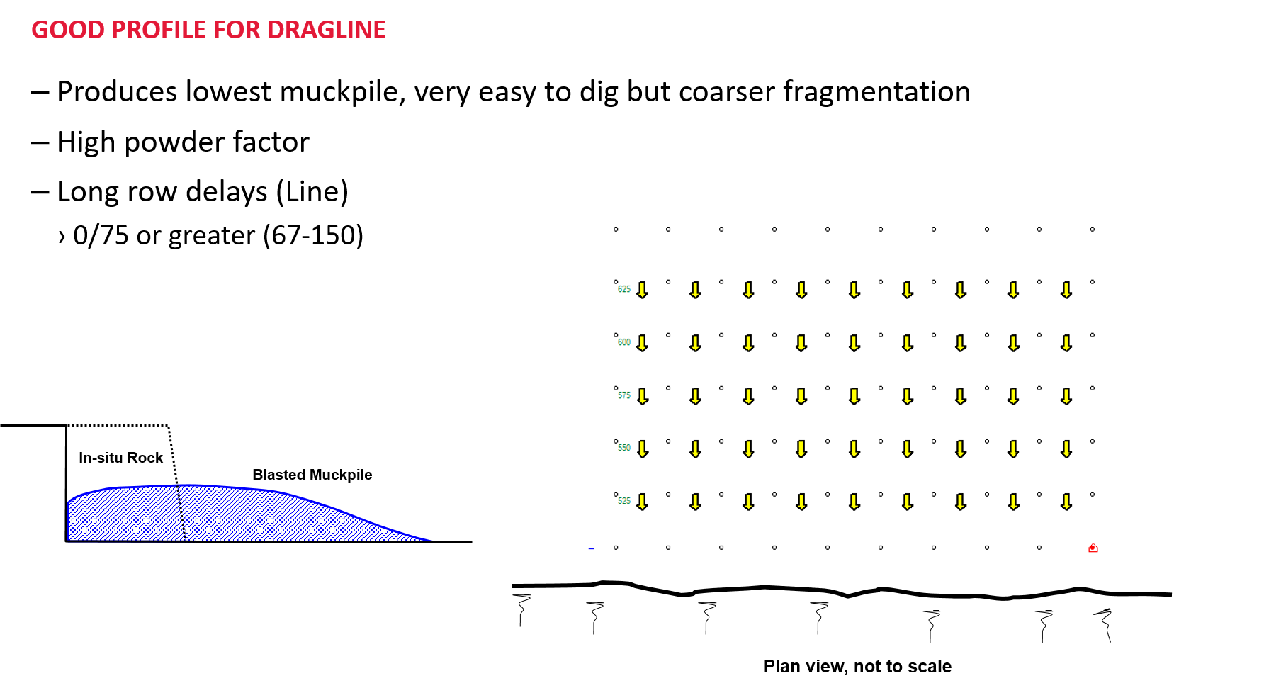
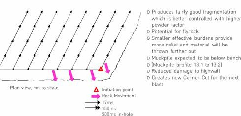
Line Blasting, row by row (Z-Profile)
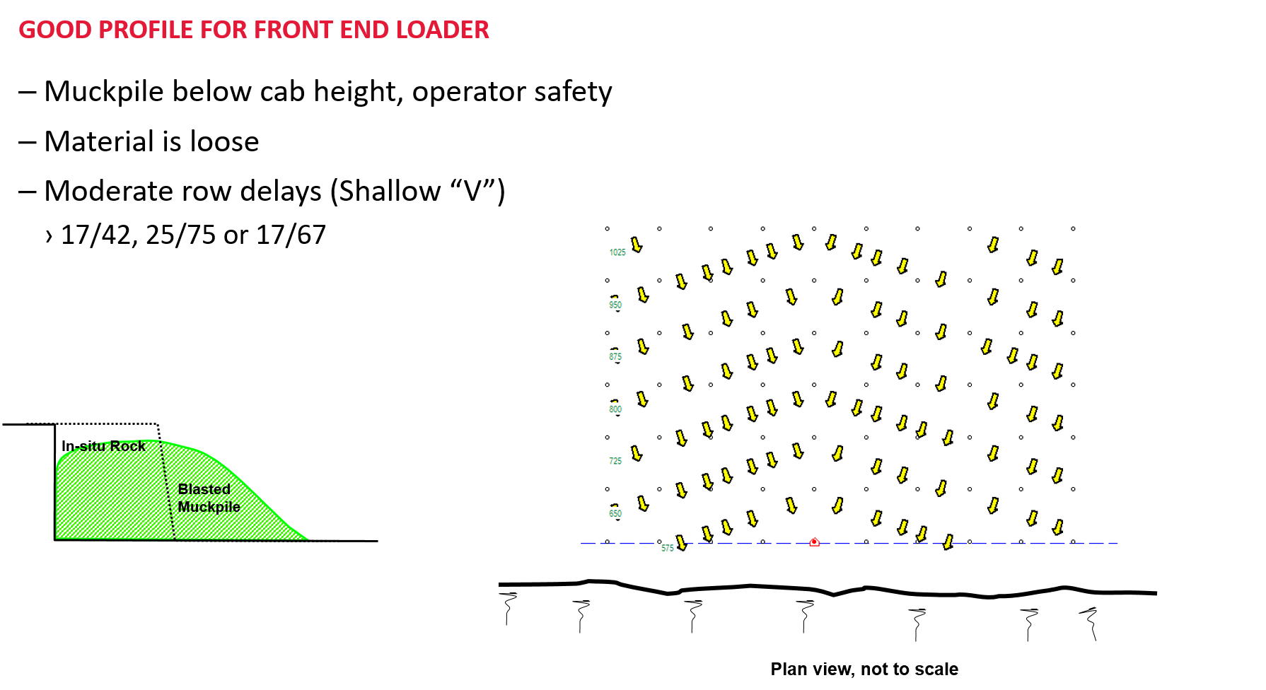
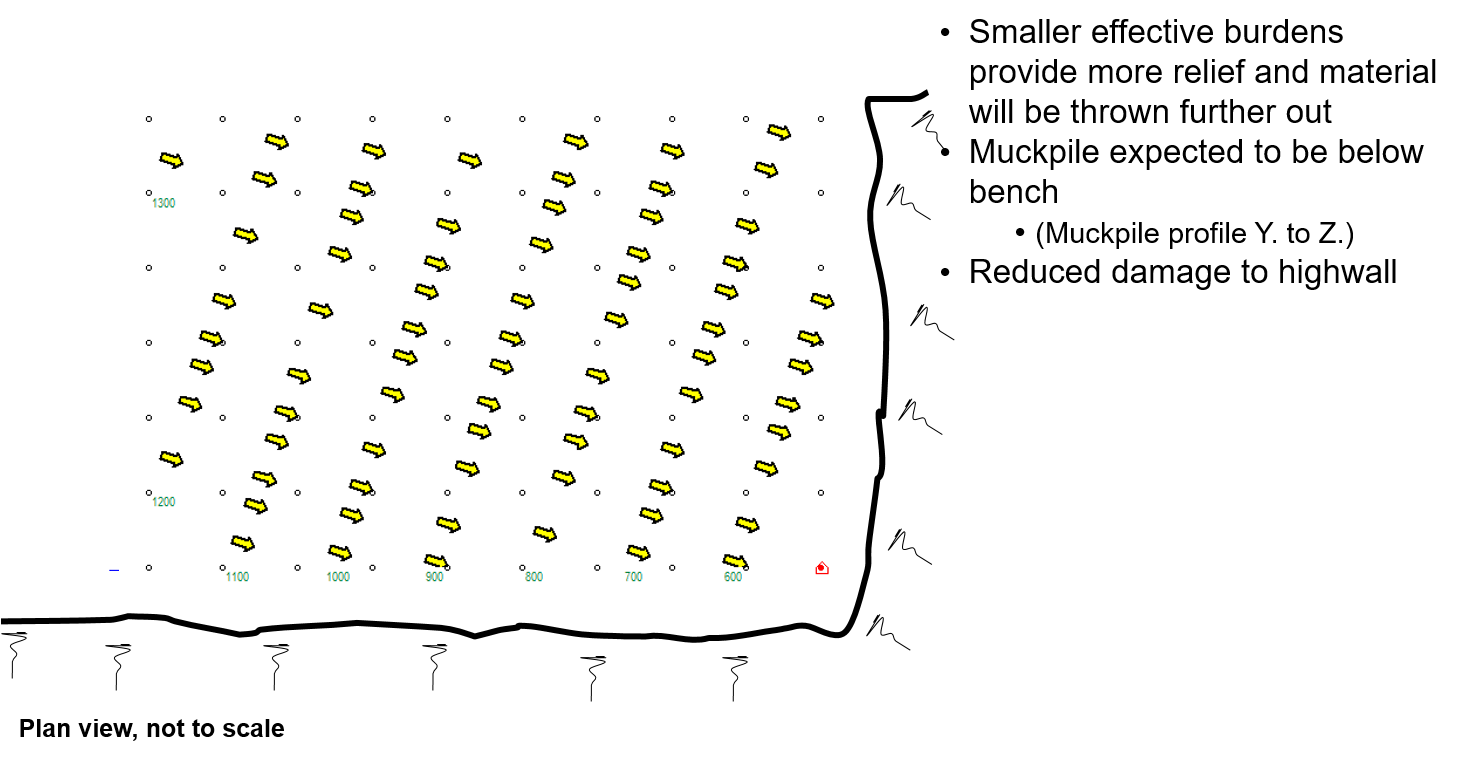
Shallow “V” (Y-Profile)
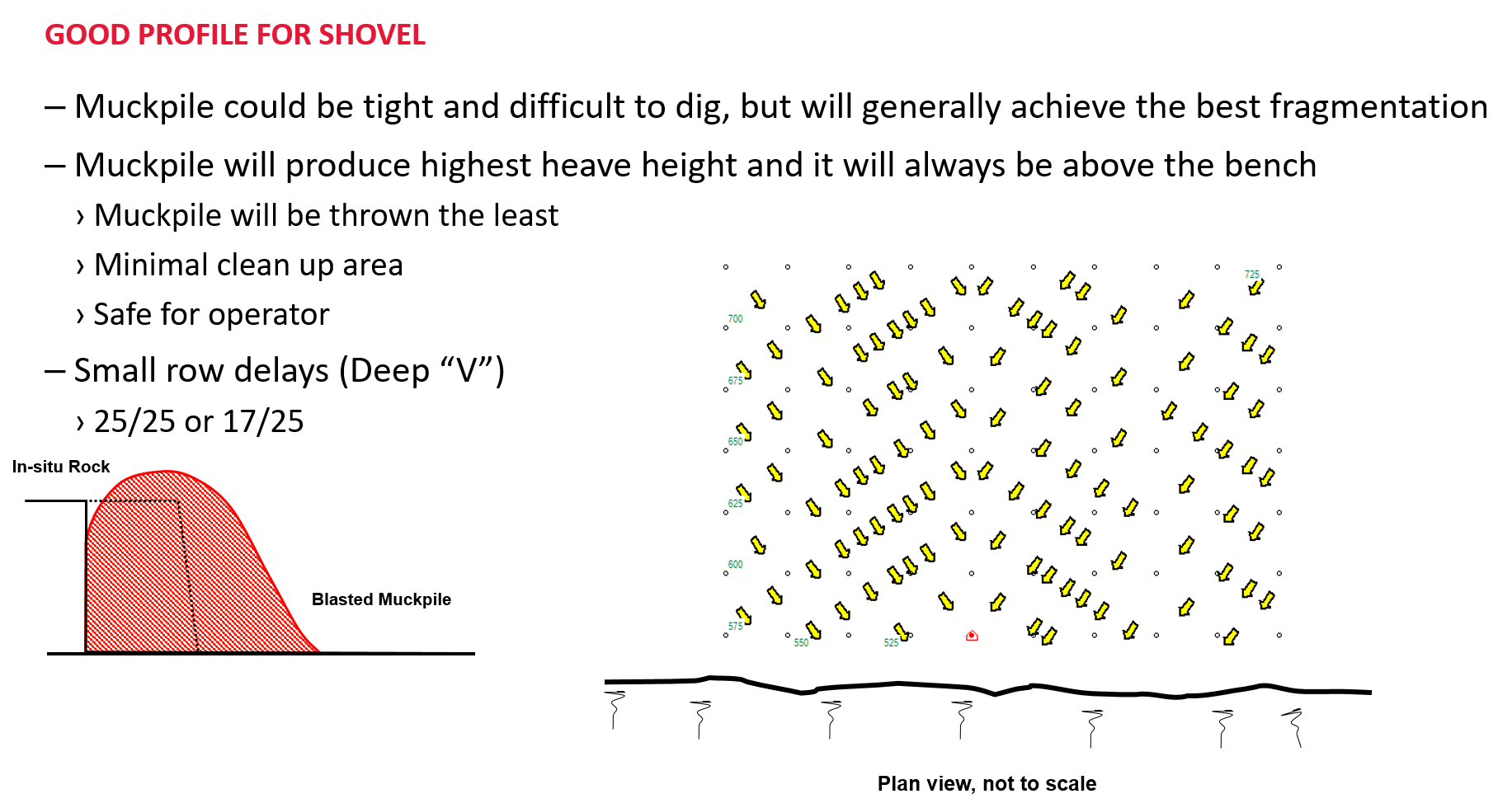
Deep “V” (X-Profile)
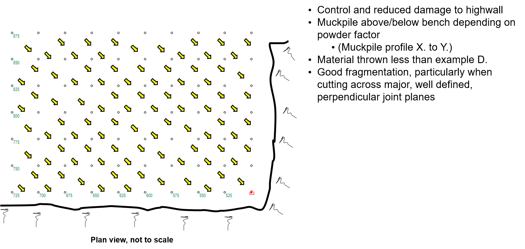
Shallow “V4” Echelon
45˚ or “V” Echelon
Corner Cut Echelon
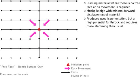
Box cut design
SECONDARY BREAKING
Drilled hole in boulder – “Popping”
| Rock thickness (m) | Hole length (m) | Boulder (m3) | Boulder | |
| Exposed | Embedded | |||
| Mass of explosives | ||||
| 0.50 | 0.30 | 0.13 | 0.01 | 0.03 |
| 0.75 | 0.45 | 0.42 | 0.04 | 0.08 |
| 1.00 | 0.60 | 1.00 | 0.10 | 0.20 |
| 1.25 | 0.75 | 1.95 | 0.20 | 0.39 |
| 1.50 | 0.90 | 3.38 | 0.34 | 0.68 |
| 1.75 | 1.05 | 5.36 | 0.54 | 1.07 |
| 2.00 | 1.20 | 8.00 | 0.8 | 1.60 |
| 2.25 | 1.35 | 11.39 | 1.14 | 2.28 |
| 2.50 | 1.50 | 15.63 | 1.56 | 3.13 |
Note: Boulder/rock exposed on bench floor/muckpile +/- 100g of explosives/m3 ; Boulder/rock embedded in the ground this may increase to +/- 200g of explosives/m3; Not recommended for boulders < 0.5m3 Where explosive cartridges are to be used, the size of the cartridges and number per hole will be determined by the hole diameter used and consideration for stemming/tamping of the blasthole
“Mud” blasting
| Rock thickness (m) | Charge mass (kg) | Powder factor (kg/m3) |
| 0.30 | 0.125 | 4.63 |
| 0.50 | 0.250 | 2.00 |
| 0.75 | 0.500 | 1.19 |
| 1.00 | 1.000 | 1.00 |
| 1.25 | 1.500 | 0.77 |
| 1.50 | 2.000 | 0.59 |
| 1.75 | 2.500 | 0.47 |
| 2.00 | 3.000 | 0.38 |
| 2.25 | 3.500 | 0.31 |
| 2.50 | 4.000 | 0.26 |
Note: The geology and rock properties will limit the breaking success at a rock thickness >1.50m. For optimum results, the charges should be covered in not less than 10x their mass in mud, at least 100 to 150mm in thickness over the charge. The mud must be free of stones, which could result in flyrock hazard.
PRIMING / DECKING
Priming
This refers to the use of one, two or more boosters and initiating systems in the blast hole to ensure the safe and reliable initiation of the explosives column, it should not be confused with decking.
Typically two or more boosters are used when:
- Hole depths > 25m
- The risk/ consequences and cost of a blast failure is non-negotiable
- Influence of geological structure on charge dislocation (cut-off initiating systems and/or explosives column resulting in potential blast failure)
- Extreme conditions where there may be mud, water or debris filled holes Use of additional booster is required by legislation
- Use of additional booster is required by legislation
The potential to control the sequence of the firing of the two or more boosters in the hole is a combination of the inherent timing scatter of the initiating system being used, the velocity of detonation of the explosive column and distance between the booster’s positions.
Deck charging
This refers to the practice of placing two or more, separate and isolated columns of explosives within a single blasthole. Decks of explosives may be isolated from one another using drill cuttings, air or any other inert material. Each explosive deck charge must contain a primer. The primer is normally located near the centre of each explosives deck.
A good starting point for the length of the decking is in the range 15 to 20 hole diameters. (The deck length should be greater than 10 hole diameters to avoid sympathetic detonation.)
Inert decks between explosives charges may consist of drill cuttings, crushed stone in the size range 6 mm to 13 mm, coarse sand, concrete or prefabricated blocks, air voids or bags. The most effective materials will be those that either lock solid under pressure and prevent communication of explosives effects, or crushable materials that absorb and dissipate explosives shock energy.
Water saturated materials tend to conduct shock waves readily and the inert deck length needs to be increased to avoid problems in such cases. The length of inert deck required in these circumstances can only be determined by trial.
Drill cuttings are typically problematic to load in wet holes as the material tends to form a thick muddy soup situation and NOT effective stemming. As a starting point the timing between decks should be greater than 25ms but less than 100ms
AIRBLAST AND GROUND (BLASTING) VIBRATIONS
“Blasting Vibration” is a general term for the diverse physical waves (manifesting as airblast and ground vibration) that arise from blasting, and impact on structures, raising concern in the public.
With the steady encroachment of residential areas onto quarrying and mining operations there has been a corresponding increase in the number of complaints about blasting operations and legal claims for damage. It is important to grasp whether these complaints are:
- Related to real damage, or
- More a matter of human alarm at the noise and rumble of blasting, although vibration levels are well below the damage thresholds, or
- Opportunistic claims
Much of the foundational research into airblast, ground vibration and consequential damage was underway from the 1950’s by the now defunct US Bureau of Mines (USBM) and continues worldwide. The USBM work is still widely accepted and is introduced here as background. In 1983 the USA OSMRE (Office of Surface Mining Reclamation and Enforcement) issued regulations based on the USBM work, modified in the light of consultation. These make good sense and form the base for AELCI's recommendations. AECI has collected data and measurements from its extensive field work and has adjusted the guide to account for the typical African structures and buildings.
More recently, with the increasing emphasis on human comfort levels and extreme caution with sensitive situations, guidelines are often more conservative. It is important to consult widely with affected parties and the authorities involved. Where a community or sensitive structures are close to the mine then the following should be adopted.
International target at the nearest public structure of concern < 5mm/s for 95% of blasts not exceeding 10mm/s.
It is to the blaster’s advantage to understand that many complaints and legal claims received as the result of blasting could have been avoided if thought and effort had been given to:
- Good public relations by ensuring both production personnel and the local community have an understanding of the nature of airblast and ground vibration
- Good blast design that minimises the generation of high amplitude, low frequency air and ground waves
- Correct use and emplacement of equipment to monitor and measure disturbance, with impartial analysis and archiving of records
- Conducting pre-blast surveys so as to minimise false claims and facilitate rapid resolution of situations
Suggested guidelines @ 50Hz
| Structure of concern | Maximum PPV (mm/s) |
| Heavily reinforced concrete structures | 120 |
| Property owned by the concern performing blasting operations where minor plaster cracks are acceptable | 84 |
| Strong masonry walls not affected by public concern | 50 |
| Commercial property in reasonable repair where public concern is not an important consideration | 25 |
| Private property if public concern is to be taken into account or if blasting is conducted on a regular and frequent basis | 10 |
Where there has been no suitable monitoring or test work, in AECI’s experience, acceptable vibration levels have always been obtained when using the following table. Unusual geological conditions could, however, result in unexpected concentration or transmissions of ground vibrations, especially in waterlogged ground and the table CANNOT therefore be viewed as infallible. If an entirely safe table for all possible conditions is required, the equation given by the USBM is applicable.
Suggested controls for charge/delay when blasting adjacent to commercial property – PPV < 25mm/s
| Distance to nearest structure (m) | Maximum charge mass/delay (kg) | Distance to nearest structure (m) | Maximum charge mass/delay (kg) |
| 1 | 0.05 | 50 | 30 |
| 2 | 0.2 | 60 | 39 |
| 3 | 0.4 | 70 | 49 |
| 4 | 0.6 | 80 | 60 |
| 5 | 0.9 | 90 | 71 |
| 6 | 1.2 | 100 | 83 |
| 7 | 1.5 | 125 | 116 |
| 8 | 1.9 | 160 | 150 |
| 9 | 2.2 | 175 | 188 |
| 10 | 2.5 | 200 | 240 |
| 16 | 4.5 | 250 | 330 |
| 20 | 7.0 | 300 | 430 |
| 25 | 10 | 400 | 670 |
| 30 | 13 | 500 | 930 |
| 35 | 17 | 1000 | 2640 |
| 40 | 21 | 1500 | 4800 |
| 45 | 25 | 2000 | 7400 |
Scaled distance
The formula is used as a “safe” and very conservative means of controlling ground vibration particularly in very “public” or sensitive areas of concern (PPV @ 5 mm/s).
Click for Calculator
- D = Distance (m)
- E = Mass of explosives per delay (kg)
NOTE: If in doubt always conduct tests
The following table shows some values based on this formula:
| Distance to nearest structure (m) | Maximum charge mass/delay (kg) | Distance to nearest structure (m) | Maximum charge mass/delay (kg) |
| 98 | 10 | 490 | 250 |
| 219 | 50 | 693 | 500 |
| 310 | 100 | 980 | 1000 |
| 438 | 200 | 1200 | 1500 |
Minimising ground vibrations
The Blaster can manage the following to assist in the minimising of ground vibrations:
- Optimise delay timing
- Reduce charge mass per delay
- Avoid overburden
- Major cause of ground vibration
- Optimise sub-drill
- Increase total blast duration
Predicting of ground vibrations
Whilst good measurement and understanding of the data is the key to control, the following formula allows a prediction to be made:
Click for Calculator
- D = Distance (m)
- E = Mass of explosives per delay (kg)
- a & b site characteristics
- Note b is a negative value
As a starting point, until the site values have been determined from measurement, the USBM gives a = 1140 and b = -1.65
Sources and influences of airblast
There are five main sources of airblast:
- The chosen initiating system in use e.g. detonating cord compared to shock tube
-
Air pressure pulse (APP)
-
Rock pressure pulse (RPP)
-
Gas release pulse (GRP)
-
Stemming release pulse (SRP)
The airblast is also influenced by:
- Topography or Surface layout
- Increase Airblast by +5 db
- Weather
- Atmospheric conditions
- Clouds
- Inversion layer
- Wind, direction
Suggested guidelines
Audible noise lies in the range of the frequency spectrum from 20 to 20 000 Hz. Airblast includes audible noise, plus frequencies below 20 Hz which cannot be heard by the human ear but can sometimes be felt by the body. Both noise and airblast decay with increasing distance. However, because low frequencies attenuate less rapidly, it is possible to have significant airblast with minimal noise at appreciable distances from the blast. Airblast without noise will cause buildings to vibrate and may result in complaints of excessive vibration at distances many kilometres from the blast site.
Overpressure is commonly recorded in decibels (dB) on a linear scale which measures all frequency components such that:
Click for Calculator
where:
- L = airblast level (dB)
- P = measured overpressure (kPa)
- P0 = reference pressure (2 x 10⁻⁸ kPa)
Recording options on industrial sound measuring instruments sometimes include the weighted scales A, B and C. These three common weighting scales discriminate against and ignore the low frequencies below the audible range for humans and are intended for human comfort and not structural damage levels. The airblast level should therefore not be confused with the guidelines of a maximum noise level in South Africa of 85dB(A) over 8 hours.
The following has been developed to help guide the Blaster and put the levels for concern into perspective (since air pressure is measured using a logarithmic scale):
| Measurement (dB) | Conversion (kPa) | Level | Comparable to |
| 100 | 0.002 | Barely noticeable. | |
| 110 | 0.006 | Readily acceptable. | Rattling of loose windows/Doors/Ceiling panels. |
| 128 | 0.050 |
Currently accepted by South African authorities as being a reasonable level for public concern. No more than 10% of measurements should exceed this value. |
|
| 134 | 0.100 |
Limit is 133 dB if lower frequency limit of the instrument is 2 Hz. Currently accepted by South African authorities that damage will not occur below this level. No measurements should exceed this value outside of the mining boundaries. |
Good Highveld thunderstorm. |
| 140 | 0.200 | Poorly mounted pictures, rattling of objects on shelves/display units, potential for these to fall. | Exceeded by strong wind gusts. |
| 170 | 6.3 | Will break a well mounted window. |
Note: dB, decibels on a linear scale
In line with international trends, AECI Mining Explosives recommends using the following when dealing with the encroachment of local communities and structures.
International target at the nearest public structure of concern < 115dB for 95% blasts, maximum of 120dB.
Control of airblast
- Create earth mounds + 3 m between mine and areas of concern
- Plant indigenous trees, grasses, bush etc. to create screen
- Avoid
- Blasting when low dense cloud base (< 2000 m) forms cover of > 50%
- Wind blowing > 10 km/h towards areas of concern
- Early or late in the day
- Use electronic detonators
- Single hole firing
- Depth of blast
- Reduce number of rows
Prediction of airblast
Whilst good measurement and understanding of the data is the key to control, the following formula allows a prediction to be made:
Click for Calculator
- L = Airblast level in deciBel (dB)
- D = Distance from blast (m)
- E = Mass of explosive per delay (kg)
The following USBM Constants for a & b can be used if no field measurements are available:
| Constraint | Value | Condition |
| a | 165 | |
| 165 + 20 | Less confinement | |
| 165 - 20 | More confinement | |
| 195 | Completely unconfined | |
| b | ≈ 24 | Decay factor |
Parameters a & b are influenced by the following factors and may be calibrated to some extent by field measurements:
- Charge mass/delay
- Delay intervals
- Drilling pattern
- Stemming length
- Direction of initiation
- Type of initiation system
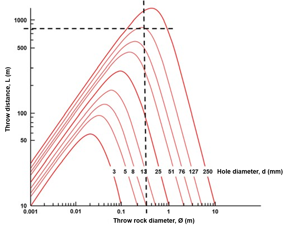
Estimation of flyrock risk zone (Lundborg)
This is an estimation of the flyrock risk zone using the calculated predicted mean size of the blasted rock and gives us a “safe” distance from the blast. The risk is the same as being struck by lightning but it does not suggest that a piece of flyrock may not travel further than the calculated risk zone.
If we take the mean size of the blasted rock to be 0.3m and read up from the x-axis to the curve representing our hole diameter, in this case 127mm, then read horizontally to the y-axis, our risk zone would be 800m for these blast parameters.
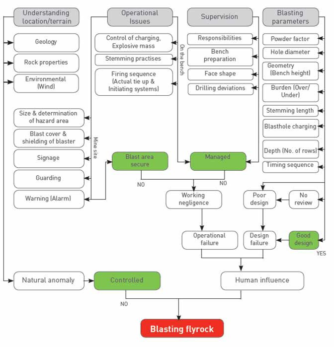
MITIGATING FLYROCK RISK - FIELD GUIDE